Map visible switches and outlets before finalizing cabinet positions. A useful record identifies the wall, the device location, the plate outline and how people use that location. Add proposed cabinet sides, backs, doors and handles on a separate layer. This reveals a physical conflict early without assuming that a device can be hidden, moved or supplied by a different circuit. The survey is a cabinet-planning record; electrical changes require their own assessment.
Give every device a place on the wall elevation
Name each wall on the room plan, then draw its elevation using a consistent horizontal reference and a stated floor reference. Give each visible device a unique letter and show that letter in the matching photograph. Record the center for location, but also the outside edges of the plate for the fit check. Note whether the measured surface is the existing finish or a surface planned for replacement.
KraftMaid includes electrical outlets and other utilities in its room-measurement process. That supports recording the existing location; it does not approve a cabinet enclosing that location or specify a required clearance.
Draw the proposed assembly at its intended depth and height. A side panel may extend farther than the box; an upper cabinet may cover a plate that sits above the planned backsplash. A counter return can change the approach to a switch even when nothing touches its face. Mark physical overlap and difficult access as different findings so that the designer knows which part of the proposal needs attention.
Design study Use the wall areas beside the sink and cabinet ends to organize a real elevation survey. This design study does not verify outlet positions, wiring, electrical compliance or clearances.
A clear center point can conceal an edge conflict
In a hypothetical elevation, a faceplate extends from 46 to 49 inches along a shared horizontal reference. Its center is at 47.5 inches. A proposed side panel occupies 48 to 49 inches at the same height, so it overlaps the plate by 1 inch even though the center lies outside the panel. Recording only the center would miss the conflict. These coordinates illustrate overlap; they are not a permitted electrical spacing rule.
Record the approach, plug and everyday task
For an outlet intended to serve a counter appliance, identify the appliance’s working position and the direction its cord approaches. Describe any existing plug projecting into the proposed cabinet area without bending or rearranging it for the sketch. For a switch, show where a person normally stands to operate it. A door or appliance that must open first can make a location inconvenient even when the front plate remains visible.
Do not infer circuit capacity, grounding, protection or concealed cable routes from a photograph. A familiar-looking receptacle also does not establish that it is appropriate for a particular appliance. Keep equipment requirements with the selected model’s documentation and flag the connection for review. The cabinet survey should make the unresolved condition legible, rather than quietly treating it as solved by a hole in a panel.
Separate a retained location from a proposed change
Use explicit labels such as existing to remain, proposed relocation and location unverified. Do not erase the existing device from the record when exploring a new cabinet arrangement. Keep its conflict visible until the proposed change has been assessed. If a plate is hidden behind existing furniture, mark the area as unobserved; guessing a center from nearby cabinetry creates a false precision that later drawings can repeat.
Prepare a marked wall elevation, a matching photograph and a short list of conflicts. Each item should name the affected panel or door, the intended appliance or switching task and the detail still needing confirmation. Leave visible devices intact during this visual survey. The resulting record lets cabinet and electrical decisions be coordinated around the same location. Finish samples can then help with appearance after the usable wall arrangement is settled.
Pure White
Cream White
Light Warm Gray
Gray
Navy
Black
Oak Tone
Dark Walnut Tone
Design study These finish studies are design references, not a list of currently orderable colors. Screens and lighting change the appearance; compare a physical sample before choosing.See all finish options →
Build a room sketch and a cabinet-run total that include the parts between the boxes. A worked example shows why the tighter measurement changes the filler allowance.
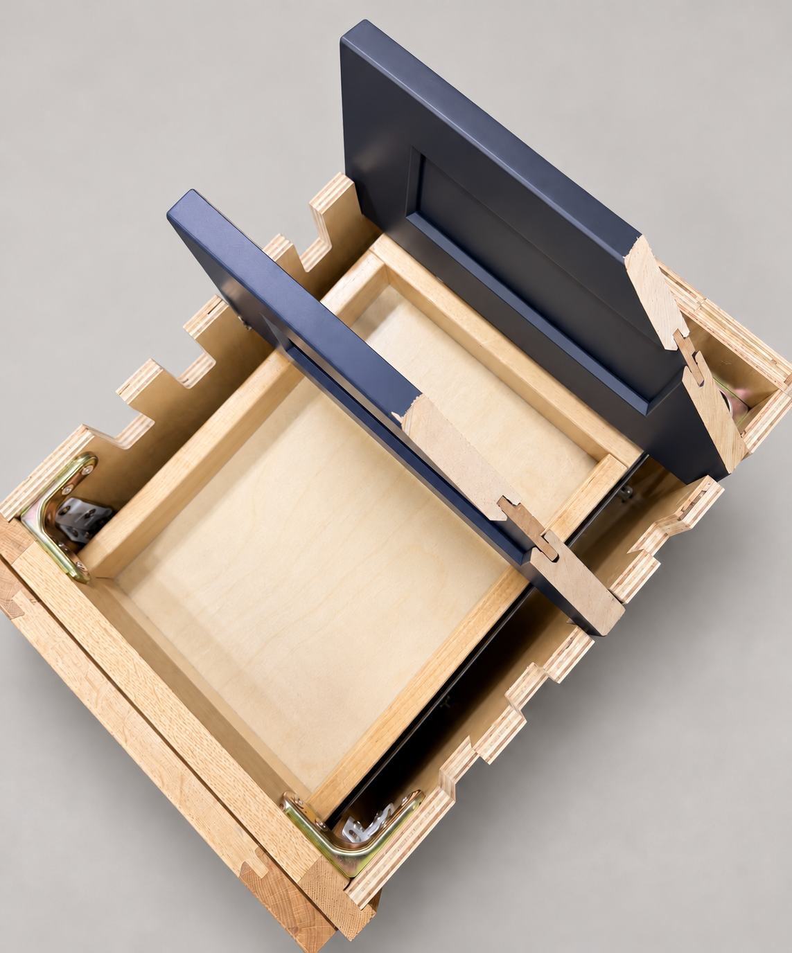
The sample shows the door frame, a separate center panel, the face frame and the cabinet box. Each component has its own place in this Shaker construction.
Shaker construction: door frame, center panel, face frame and cabinet box. The cutaway helps locate these parts; confirm each material in the specifications for the selected cabinet.
01 / Door frame
The Shaker door has rails and stiles around a separate center panel. The frame and center panel are different components; confirm their materials in the specifications for the selected cabinet.
02 / Face frame
The face frame surrounds the opening at the front of the cabinet box and sits behind the doors. The face frame, door frame and cabinet box are separate parts.
03 / Cabinet box
The sample exposes the cabinet sides, interior surfaces and layered edges. The image does not establish the wood species or material specification of a selected cabinet.