Choose sink-base storage from the usable space around the actual services, rather than from the cabinet’s outside width. Pipes, the underside of the bowl, valves and any installed equipment occupy different depths and heights. The remaining space may be divided into narrow pockets. Record those boundaries before comparing a removable bin, shelf or pullout, and preserve the ability to reach the components that need attention.
Record visible components without changing them
Open the cabinet normally and photograph the interior from the front and from accessible side angles. Name what you can identify and mark uncertain components as unknown. Draw the cabinet’s inside floor and the visible outline of the sink, drain connections, valves, hoses and equipment. Record where each outline begins and ends relative to the same interior references. Leave connections and equipment in place; this is an observation task, not a plumbing adjustment.
KraftMaid’s measuring guidance includes locating water and drain connections. A storage survey adds the occupied volume around those locations. A connection center on the back wall cannot describe every projection farther forward.
Map the space at the height the organizer will use
A plan view shows the footprint, while a front view shows which areas are occupied above the cabinet floor. Add a side sketch where a pipe changes direction or a bowl projects downward. Measure the organizer as a complete assembly, including its frame and any contents extending above it. An open patch on the floor does not prove that a tall container can occupy the same location.
ABCD
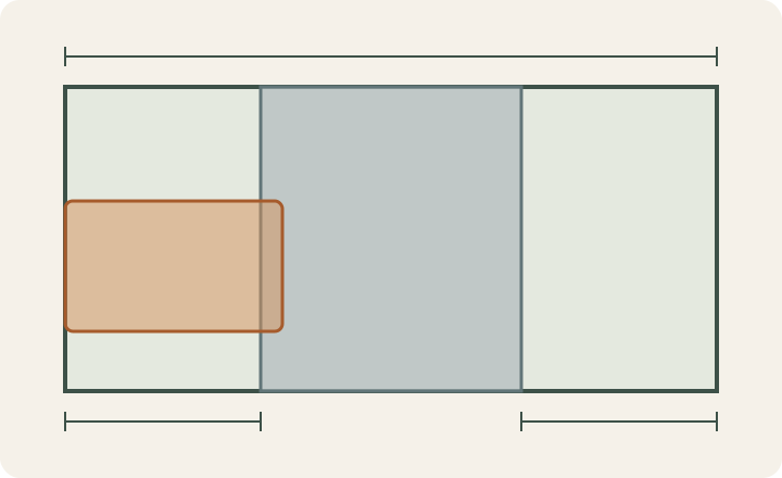
Diagram The gray region represents an assumed occupied service volume at the storage height being checked. The orange organizer is wider than either side pocket. The simplified geometry is not a plumbing or installation layout.
A
Full interior width used in the example.
B
Assumed occupied service region.
C
Organizer overlaps the service region when placed in the left pocket.
D
Separate right pocket cannot be combined with the left to fit a rigid organizer.
Do not add disconnected widths into a usable opening
In a hypothetical cabinet with 30 inches of usable inside width, a centered service envelope occupies 12 inches through the height and depth needed by the proposed storage. That leaves 9 inches on each side. Although the free widths add to 18 inches, neither pocket accepts a 10-inch-wide organizer; it exceeds each pocket by 1 inch. The example assumes the central region cannot be used or crossed. It supplies no standard cabinet size or required plumbing clearance.
Check insertion, opening and removal separately
An organizer may fit in its final location yet fail to pass through the door opening. Hinges and a center stile can narrow the entry. A pullout also needs an unobstructed travel path, not just a clear parked position. Trace its frame and the intended contents from closed to open. A hose behind it should not be treated as something that will conveniently move aside every time the organizer operates.
Keep service access distinct from everyday storage access. Being able to lift out a bottle does not show that a valve can be reached or equipment serviced. Record which items can be removed simply and which mounting frames would remain. Required access and clearances belong to the actual equipment and installation requirements; do not invent a universal gap from the available space. Any proposed pipe relocation changes the survey and needs separate confirmation.
Compare organizers against the same recorded boundaries
Mark each candidate as fitting the observed pocket, conflicting with a named component or awaiting a missing measurement. A removable container may suit an irregular zone better than a full-width mechanism, but its loaded height and removal route still matter. Preserve any uncertain area rather than awarding it to storage. If the sink or equipment will change, label the old survey as existing and compare the new documented envelope before selecting accessories.
Your useful handoff is an interior sketch with matched photographs, the occupied regions, the door-entry shape and the proposed organizer’s complete dimensions. Include the operating and service-access questions still open. This allows a specific fit decision instead of a promise based on nominal cabinet width. The finish reference below relates to visible cabinet coordination; it does not change the interior space available for storage.
Pure White
Cream White
Light Warm Gray
Gray
Navy
Black
Oak Tone
Dark Walnut Tone
Design study These finish studies are design references, not a list of currently orderable colors. Screens and lighting change the appearance; compare a physical sample before choosing.See all finish options →
Build a room sketch and a cabinet-run total that include the parts between the boxes. A worked example shows why the tighter measurement changes the filler allowance.
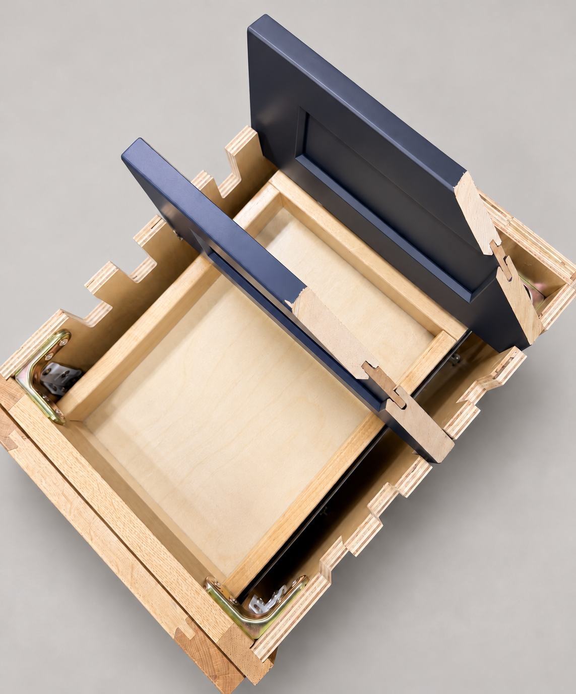
The sample shows the door frame, a separate center panel, the face frame and the cabinet box. Each component has its own place in this Shaker construction.
Shaker construction: door frame, center panel, face frame and cabinet box. The cutaway helps locate these parts; confirm each material in the specifications for the selected cabinet.
01 / Door frame
The Shaker door has rails and stiles around a separate center panel. The frame and center panel are different components; confirm their materials in the specifications for the selected cabinet.
02 / Face frame
The face frame surrounds the opening at the front of the cabinet box and sits behind the doors. The face frame, door frame and cabinet box are separate parts.
03 / Cabinet box
The sample exposes the cabinet sides, interior surfaces and layered edges. The image does not establish the wood species or material specification of a selected cabinet.