Check a window crank and faucet as moving objects, at the heights where they actually overlap. A faucet can clear a parked crank and still block its rotation; a faucet lever can enter the crank’s path only when water is being adjusted. The window sash has its own movement as well. Record these paths separately before deciding whether the sink, faucet or window arrangement needs to change.
Identify what moves and how it is used
Operate the existing window carefully through its normal range where unobstructed. Observe the crank or latch, the sash and the hand position needed to use the control. Record the control pivot and its height above the planned counter. For the proposed faucet, obtain the actual drawing and identify the body, spout, operating lever and any moving hose component relevant to that location. A photograph of a similar faucet does not establish the selected one’s geometry.
IKEA’s window measurement scope includes space needed for full opening. Here that check is extended to the relationship with the selected faucet, rather than assuming the visible gap is sufficient.
A top view shows whether the paths overlap horizontally; a side view shows whether they occupy the same height. Both are necessary. A crank may pass above a low faucet base yet hit an upright lever. Conversely, shapes that cross in plan might sit at different heights. Measure from the same finished counter or sill reference, and include projecting window trim when establishing the distance from the wall.
Distinguish the envelope of the hardware from the room your hand needs to grip it. A mathematical gap between metal parts can still leave an awkward operating motion. The appropriate usable space depends on the actual control and person using it. There is no universal clearance supplied here. The purpose is to test the complete action before a fixed faucet position becomes difficult to change.
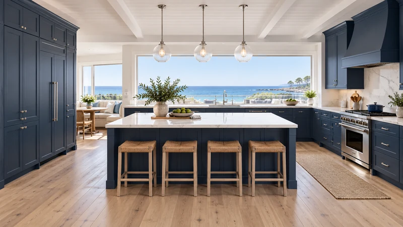
Design study The faucet occupies the area where a window control could need access. This design study does not show the control mechanism, confirm that the window opens or prove clearance around the faucet.
A handle position can change the result
In a hypothetical simplified check at the same height, a crank-tip path extends 3 inches from its pivot. The nearest fixed faucet body is 4 inches from that pivot, leaving 1 inch between the assumed envelopes. Suppose the faucet lever moves 2 inches toward the pivot. Its nearest point is then 2 inches away, entering the crank envelope by 1 inch. The initial body-only check would miss the conflict. These are teaching assumptions, not manufacturer dimensions or a recommended gap; actual shapes and the user’s hand also need review.
Mock up the complete action at the intended position
Use a dimensionally reliable outline or appropriate mock-up of the selected faucet at its planned height and setback. Show the lever’s operating positions, not only its resting silhouette. Check the window control and sash without forcing either against the mock-up. Include the person’s usual approach to the sink and the way the control is gripped. A test with the faucet shifted to an easier spot is useful only if that spot is a real option in the sink and counter plan.
Possible responses include a different faucet geometry, an approved position change or a window-control option confirmed for the actual window. Do not assume a removable or folding crank is compatible with every mechanism. Moving the faucet must also be checked against the selected sink, mounting location and surrounding components. Each alternative should solve the operating conflict while preserving the other functions of the sink area.
Keep the check with the final sink elevation
Record the window model if known, control type, pivot location, faucet model, mounting position and the operating states tested. Keep the plan and side views with photographs of the mock-up. Flag any unseen sash movement or missing product drawing for verification. This record is more useful than a note saying “faucet clears window,” because it shows what was actually checked. The finish studies below are unrelated to these moving clearances.
Pure White
Cream White
Light Warm Gray
Gray
Navy
Black
Oak Tone
Dark Walnut Tone
Design study These finish studies are design references, not a list of currently orderable colors. Screens and lighting change the appearance; compare a physical sample before choosing.See all finish options →
Build a room sketch and a cabinet-run total that include the parts between the boxes. A worked example shows why the tighter measurement changes the filler allowance.
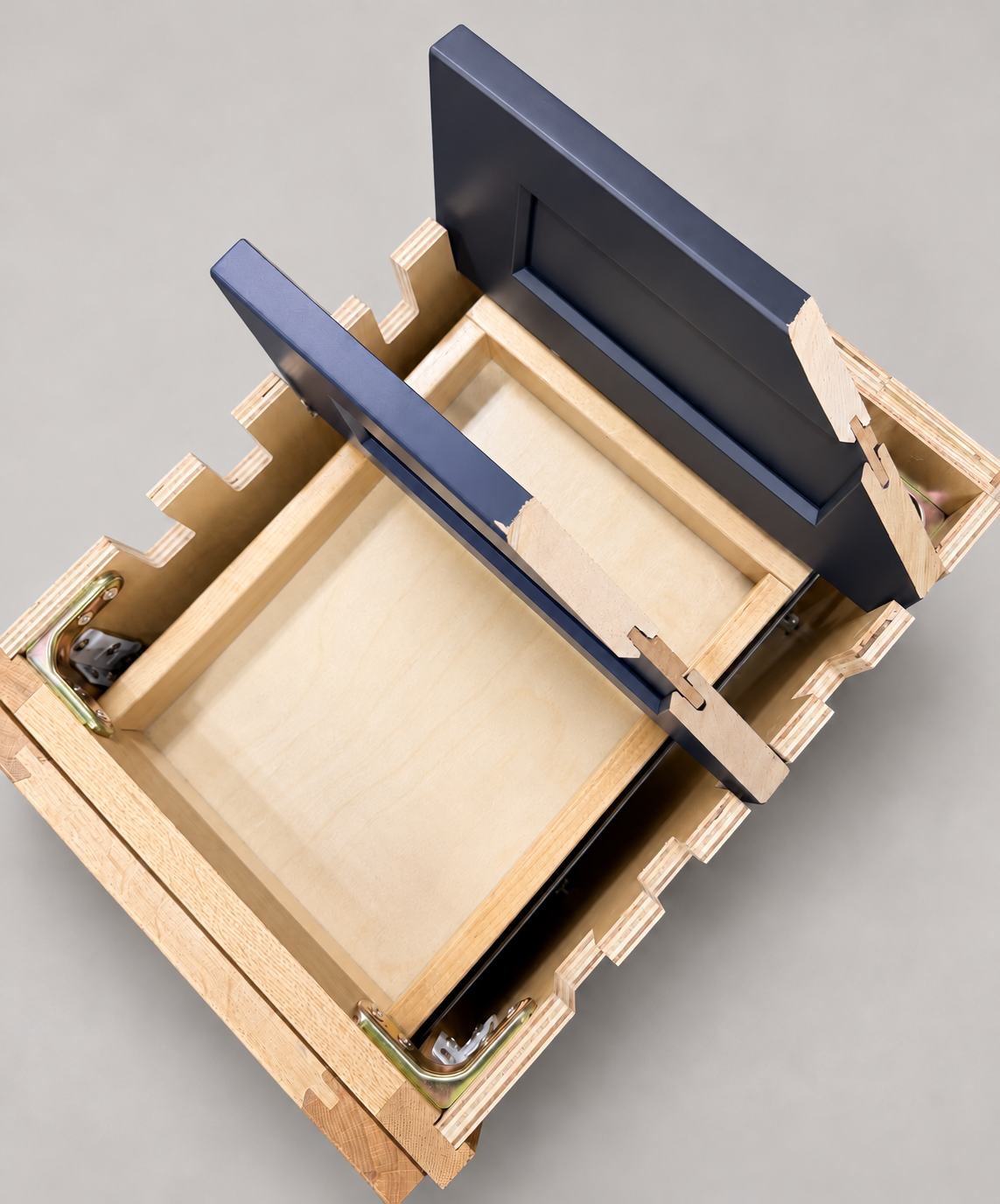
The sample shows the door frame, a separate center panel, the face frame and the cabinet box. Each component has its own place in this Shaker construction.
Shaker construction: door frame, center panel, face frame and cabinet box. The cutaway helps locate these parts; confirm each material in the specifications for the selected cabinet.
01 / Door frame
The Shaker door has rails and stiles around a separate center panel. The frame and center panel are different components; confirm their materials in the specifications for the selected cabinet.
02 / Face frame
The face frame surrounds the opening at the front of the cabinet box and sits behind the doors. The face frame, door frame and cabinet box are separate parts.
03 / Cabinet box
The sample exposes the cabinet sides, interior surfaces and layered edges. The image does not establish the wood species or material specification of a selected cabinet.