Measure a bay-window recess as a changing outline. Its central depth does not establish how far a rectangular cabinet or storage unit can extend into it. Draw the angled returns, identify a fixed line across the opening and record perpendicular depths at the actual edges of the proposed footprint. Then check the complete shape at the intended height. A deep central point can coexist with side corners that block the unit.
Establish a baseline across the opening
Choose identifiable endpoints across the room-side opening and record them on the plan. This baseline is a reference for locating the recess, not necessarily the future counter edge. Map each change of direction in the finished boundary behind it. Include projecting trim or a sill if it occupies the proposed space. Do not assume the bay is symmetrical merely because its center window looks balanced in a photograph.
IKEA’s window survey includes frame, sill and operating-space measurements. The bay profile here is an editorial method for applying those separate boundaries to an irregular footprint.
Record perpendicular depths from the baseline to the boundary at the center and at the left and right limits of the intended cabinet or storage unit. The side positions matter: moving an edge toward an angled return can reduce available depth. Label the measuring stations instead of listing disconnected lengths. If the proposed unit changes width or position, its side checks must be updated as well.
Repeat the relevant outline at the height being considered. A sill can project farther than the wall below it, while a window control or moving sash can occupy space above the surface. A plan taken at floor level does not automatically describe the countertop or upper storage zone. Keep those outlines distinct, with their reference heights, until the proposed assembly can be compared with all of them.
ABCD
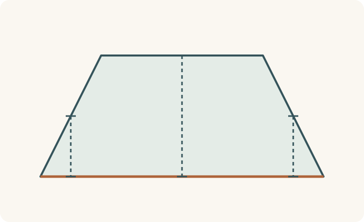
Diagram The dashed depths share the same opening baseline. The side stations can limit a rectangular footprint even when the center is deeper. Hypothetical geometry only; not a field survey or a fabrication drawing.
A
Left station at the proposed footprint edge.
B
Central depth of the recess.
C
Right station at the proposed footprint edge.
D
Common opening baseline; not a specified counter edge.
Test the side corners, not only the center
In a hypothetical example, depth behind the opening baseline is 20 inches at the center and 10 inches at each proposed side station. A rectangular storage footprint extending 18 inches behind that line would leave 2 inches at the center but exceed the side depth by 8 inches. The rectangle therefore does not fit the stated footprint. These are assumed teaching dimensions; the diagram illustrates the same relative depth relationship without specifying a product, window angle or installation detail.
Now reverse the question: how much width is available where the proposed back edge would sit? In an angled bay, the opening width and the width deeper inside are different. Mark that rear line on the profile and compare the full assembly width, including separately required side pieces. This catches a unit that passes the front opening but runs into the angled returns farther back. Do not interpret passage through the opening as proof that the complete footprint fits.
Choose a layout response to the actual outline
A shallower or narrower approved storage unit, a different position or leaving part of the recess open may be more useful than trying to occupy every corner. Compare the storage that remains with the reach needed to use it. A deep surface behind a sink can become difficult to reach even if it fits geometrically. Any surface spanning the recess also needs its actual support and fabrication requirements resolved separately; the plan outline alone does not establish them.
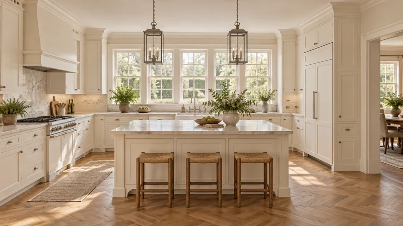
Design study The visible frame and counter junction identifies the kinds of boundaries to record. This design study is not a measured bay-window example, and its outline must not be used as the profile of a different room.
Hand over a profile, not a guessed template
Provide the baseline endpoints, corner locations, station depths, reference heights and photographs of the trim and controls. Show the proposed rectangular footprint on the same plan and identify concealed sections. Keep the final field verification and any fabrication template as separate deliverables; a homeowner’s planning sketch is not a cut-ready shape. The designer can then compare usable arrangements before cabinet selection, while the finish reference below remains a visual aid only.
Pure White
Cream White
Light Warm Gray
Gray
Navy
Black
Oak Tone
Dark Walnut Tone
Design study These finish studies are design references, not a list of currently orderable colors. Screens and lighting change the appearance; compare a physical sample before choosing.See all finish options →
Build a room sketch and a cabinet-run total that include the parts between the boxes. A worked example shows why the tighter measurement changes the filler allowance.
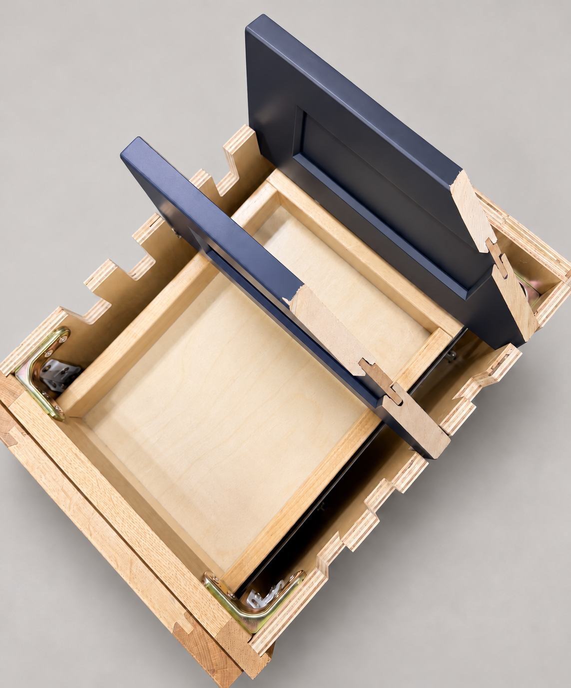
The sample shows the door frame, a separate center panel, the face frame and the cabinet box. Each component has its own place in this Shaker construction.
Shaker construction: door frame, center panel, face frame and cabinet box. The cutaway helps locate these parts; confirm each material in the specifications for the selected cabinet.
01 / Door frame
The Shaker door has rails and stiles around a separate center panel. The frame and center panel are different components; confirm their materials in the specifications for the selected cabinet.
02 / Face frame
The face frame surrounds the opening at the front of the cabinet box and sits behind the doors. The face frame, door frame and cabinet box are separate parts.
03 / Cabinet box
The sample exposes the cabinet sides, interior surfaces and layered edges. The image does not establish the wood species or material specification of a selected cabinet.