Record a column or boxed projection as a footprint with several faces, not as a symbol placed approximately on the kitchen plan. Locate its front and side edges relative to the intended cabinet fronts. Then check doors and drawers in motion. A closed cabinet can fit beside a projection while its drawer travels into the space occupied by it. The visible shape also does not establish whether a projection is structural or can be altered.
Locate each face from a fixed room reference
Choose recognizable wall intersections or other fixed references and record where the projection begins and ends in both plan directions. Measure its finished face, including any trim that will remain. Name the faces on the sketch so a dimension to the near edge cannot be mistaken for one to the far edge. If cabinetry hides a return, mark that edge as unverified rather than extending the visible face by eye.
IKEA’s room measurement scope includes obstacles such as columns. The useful requirement here is a located obstruction, without inferring what supports it or what is concealed inside.
A projecting base, decorative band or upper enclosure can occupy a different footprint from the main shaft. Record the outlines that overlap the proposed cabinets and their moving fronts. A floor-level sketch alone can miss an obstruction at drawer or handle height. Likewise, a reading taken above existing base cabinets may not show the shape behind them. Keep these observations separate until the complete cabinet envelope can be checked.
Show the intended cabinet-front line beside the column. Identify whether a door swings toward the return or a drawer slides alongside it. Include handles and any applied side panel in the comparison. A nominal cabinet depth does not describe every projecting part. The question is which components enter the same strip of space as the column during normal use.
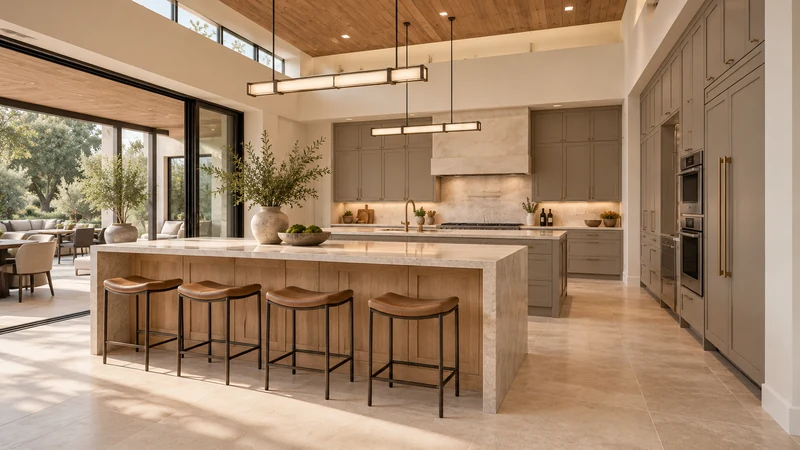
Design study The visible return beside the tall cabinetry illustrates the faces that need separate locations. This design study does not identify a structural column, hidden contents or verified operating clearances.
Check travel where the paths actually overlap
In a hypothetical plan at the same height, a column occupies part of the drawer’s travel strip beginning 18 inches in front of the closed drawer-front reference. The selected drawer would extend 22 inches from that reference. Its intended path reaches 4 inches into the obstruction. The closed arrangement may look clear, but full travel fails. These assumed distances are not normal drawer specifications or required clearances; actual lateral overlap, hardware travel and hand access must be checked for the selected cabinet.
Compare responses without assuming the column can move
A different cabinet configuration, a deliberate offset or a revised drawer location may avoid the conflict. Check what happens to storage and access in each case. Replacing a drawer with a door is useful only if the door itself opens and the contents can be removed. Shifting the cabinet can affect its alignment with the neighboring run, counter and appliances. Keep those relationships on the same drawing so the obstruction is resolved rather than passed along.
Do not remove trim, cut into a boxed projection or assume it is decorative from an image. Any proposed alteration needs the appropriate site assessment and project scope. The cabinet layout can proceed using the retained footprint while that question is unresolved. A clean drawing with a smaller guessed column is not a verified basis for selecting cabinet widths.
Hand over the obstruction and the operating check together
Provide a dimensioned footprint, named faces, height-specific changes, photographs and the fixed references used. Overlay the selected cabinet fronts and their operating paths, then identify the exact configuration being compared. Keep hidden edges and possible structural questions visible as unresolved items. This gives the designer a useful physical constraint and a defined access task. The finish palette can support the appearance of the resulting arrangement after the column relationship is established.
Pure White
Cream White
Light Warm Gray
Gray
Navy
Black
Oak Tone
Dark Walnut Tone
Design study These finish studies are design references, not a list of currently orderable colors. Screens and lighting change the appearance; compare a physical sample before choosing.See all finish options →
Build a room sketch and a cabinet-run total that include the parts between the boxes. A worked example shows why the tighter measurement changes the filler allowance.
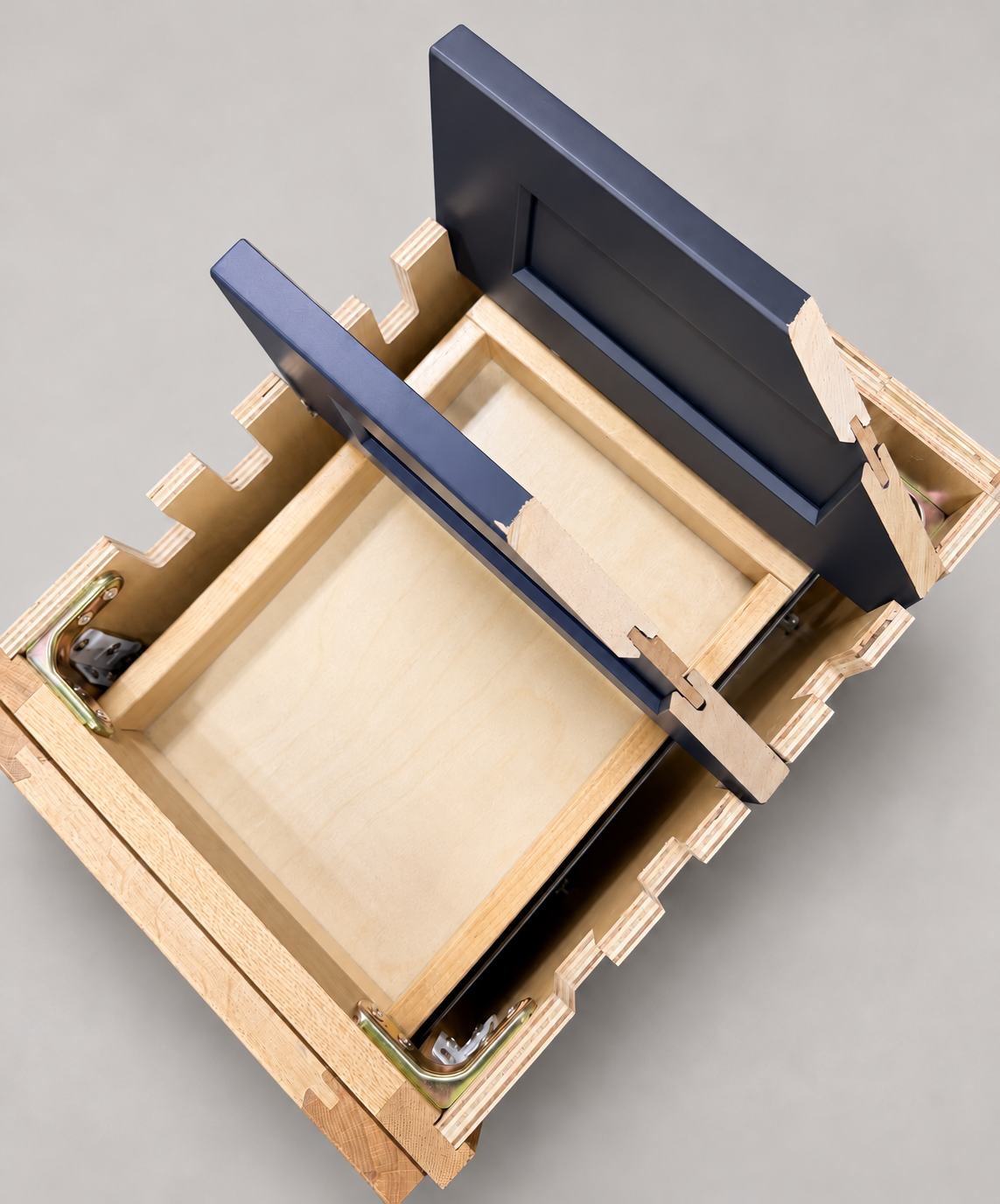
The sample shows the door frame, a separate center panel, the face frame and the cabinet box. Each component has its own place in this Shaker construction.
Shaker construction: door frame, center panel, face frame and cabinet box. The cutaway helps locate these parts; confirm each material in the specifications for the selected cabinet.
01 / Door frame
The Shaker door has rails and stiles around a separate center panel. The frame and center panel are different components; confirm their materials in the specifications for the selected cabinet.
02 / Face frame
The face frame surrounds the opening at the front of the cabinet box and sits behind the doors. The face frame, door frame and cabinet box are separate parts.
03 / Cabinet box
The sample exposes the cabinet sides, interior surfaces and layered edges. The image does not establish the wood species or material specification of a selected cabinet.