Coordinate an over-the-range microwave with the upper cabinet and the selected range
Set out the cooking surface, microwave and upper cabinet together. The mounting arrangement, permitted vent route and both appliances’ instructions determine whether the proposed position works.
Choose the range and over-the-range microwave before fixing the cabinet above them. Put both installation instructions beside one section through the cooking area. A microwave that fits the opening width can still conflict with the range requirements, mounting arrangement, exhaust path or usable reach. This planning task concerns a purpose-built over-the-range appliance; it does not authorize suspending an ordinary countertop microwave.
Draw the vertical relationships on one section
Mark the finished floor, actual cooking surface, underside of the upper cabinet and proposed microwave top and bottom. Keep these reference surfaces distinct when transferring requirements from the manuals. A dimension measured above the cooking surface cannot be compared directly with one measured from the floor or cabinet underside. Include the range’s intended installed position, not just its catalog image.
Read the applicable requirements for both selected appliances and the surrounding cabinet configuration. Do not select whichever instruction seems easier to satisfy. If the proposed combination cannot meet both, or the instructions leave compatibility unclear, resolve the model pairing or cabinet position before approving it. This page supplies no universal mounting height or cooking-surface clearance.
Check what the cabinet actually presents to the installer
Show whether the cabinet underside is flat or recessed and identify face-frame edges, bottom panels and nearby shelf locations. These features can change how the installation detail is carried out. Have the installer assess the actual cabinet and wall against the selected appliance’s support and fastening instructions; a finished surface alone does not establish suitable support. Do not infer a fixing detail from the diagram here.
GE explains that its top and rear templates locate mounting, vent and cord provisions, with the rear template used for rear outdoor venting. Its replacement-template information also distinguishes a reduced copy from a full-size template. Use the exact model documents and verify the template’s intended scale and reference edges before anyone marks the cabinet.
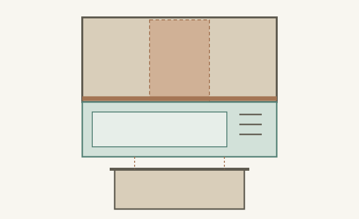
Diagram The drawing illustrates one hypothetical upward exhaust reservation. It is not a duct design, bolt pattern, support detail or clearance prescription. Other permitted exhaust arrangements have different requirements; obtain the actual geometry from the selected appliances and installation documents.
A
Reserve the selected exhaust and service route before adding storage.
B
The cabinet attachment interface needs its own verified detail.
C
The installed microwave envelope includes the lower edge.
D
Read the cooking-surface relationship from the actual model instructions.
Choose the permitted exhaust arrangement before using the cabinet interior
Establish the exhaust option supported by the exact microwave and appropriate for the project. For an approved upward route, draw the actual adapter and duct path through the upper area before locating shelves or stored items. For a rear route, investigate the wall path and affected construction. Recirculation is an option only when supported for the selected arrangement; it is not an automatic solution to a blocked outdoor route.
Keep instructed air outlets, filters, electrical access and service provisions available. A shelf drawn through a duct reservation is a real conflict even if the door closes. Record unresolved routing or support questions separately from ordinary storage dimensions so they remain visible when the cabinet drawing is reviewed.
Test a replacement by its installed envelope
Imagine keeping the existing upper cabinet while choosing a taller microwave that appears the same width. With its top held at the same intended position, its lower edge moves closer to the cooking surface. The old installation does not prove the new relationship is acceptable. Raising the upper cabinet may affect reach, attachment details and the exhaust connection, so it requires a coordinated revision rather than an isolated height change.
GE specifically directs replacement installations to use the new microwave’s model-specific bracket and new supplied hardware and exhaust adapter. Similar width or familiar old holes do not justify assuming the previous mounting equipment can be retained.
Check use after resolving the installation conditions
With the cooking area cold, test door swing, controls and a representative cold container using a suitable mock-up or display. Assess the actual user’s reach and where the container will be set down. This use trial does not validate the support, exhaust or installation clearances. Keep neighboring cabinet doors and any protruding trim in the test.
Retain the exact appliance pair, current instructions, shared section, selected exhaust route and the installer’s resolved cabinet attachment detail. Recheck them when either appliance or the cabinet position changes. The useful result is a coordinated arrangement whose open questions are resolved before cabinet work proceeds.
Pure White
Cream White
Light Warm Gray
Gray
Navy
Black
Oak Tone
Dark Walnut Tone
Design study These finish studies are design references, not a list of currently orderable colors. Screens and lighting change the appearance; compare a physical sample before choosing.See all finish options →
A cabinet opening that accepts the microwave body is not proof of an approved enclosure. Verify the model, any required matched kit and the complete airflow and opening details first.
An outer front can cover a gap without confirming the required opening, support or attachment. Match the exact appliance and accessory configuration to the cabinet detail behind it.
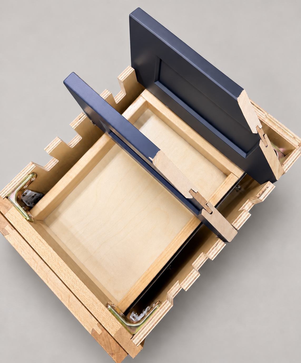
The sample shows the door frame, a separate center panel, the face frame and the cabinet box. Each component has its own place in this Shaker construction.
Shaker construction: door frame, center panel, face frame and cabinet box. The cutaway helps locate these parts; confirm each material in the specifications for the selected cabinet.
01 / Door frame
The Shaker door has rails and stiles around a separate center panel. The frame and center panel are different components; confirm their materials in the specifications for the selected cabinet.
02 / Face frame
The face frame surrounds the opening at the front of the cabinet box and sits behind the doors. The face frame, door frame and cabinet box are separate parts.
03 / Cabinet box
The sample exposes the cabinet sides, interior surfaces and layered edges. The image does not establish the wood species or material specification of a selected cabinet.