A bowed wall needs a profile of its changing position, not a single depth measurement. Locate the part that projects farthest into the proposed cabinet footprint, then record the areas that recede behind it. This gives the designer and installer a real boundary to work with. Averaging the readings makes the wall look straighter on paper while preserving the physical obstruction that matters on site.
Identify which cabinet run the wall can affect
Start with the proposed cabinet locations. A bump behind a base cabinet, a recess behind a tall unit and an irregular patch above the counter may affect different parts of the plan. Sketch those locations separately. Do not assume a reading taken above the old backsplash describes the concealed wall below. A decorative surface can also project beyond the underlying wall, so note which layer is actually being measured and whether it will remain.
KraftMaid’s preparation guidance calls for checking wall unevenness before installation. The survey here documents that condition without selecting an installation correction.
Measure from a straight reference, not from the previous bump
Have a straight reference established clear of the wall and identify it on the sketch. The reference must stay fixed while readings are taken. Measure perpendicular distances back to the wall at named stations along the proposed run. If each reading begins at a different nearby surface, the values will not describe a common profile. Label the stations by recognizable room features or marks that can be found again.
Keep measurements at the same elevation together. Where base cabinets, upper cabinets and a tall unit occupy different heights, obtain the relevant profiles and name each one. A wall that changes position from bottom to top may also be leaning; that is a separate condition from its horizontal bow. Concealed areas remain unverified until they can be inspected. A smooth existing cabinet front does not establish the shape of the wall behind it.
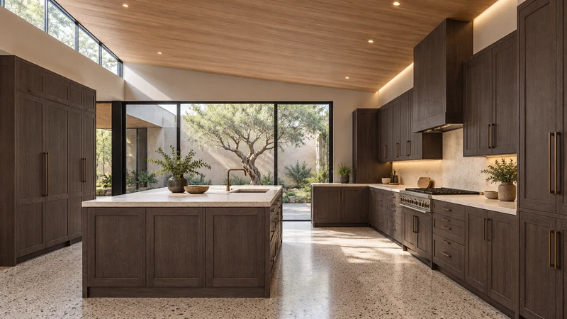
Design study Follow the aligned drawer fronts along the right-hand run. That visible alignment is a planning goal; this design study cannot reveal whether the hidden wall is straight or how the cabinets are supported.
A smaller gap can reveal the larger obstruction
For a hypothetical example, a fixed straight reference is 2 inches from the wall at both ends of a run and 1 inch from the wall at its middle. The middle therefore projects 1 inch farther toward the reference than the ends. Using only the end readings would miss the obstruction; averaging them with the middle reading would not remove it. These numbers describe assumed geometry only. They are not an acceptable wall tolerance, a required cabinet offset or a recommendation for shim thickness.
Review the consequence at the front and at both ends
The installation team may need to evaluate wall preparation or a cabinet alignment that accounts for the projection. Either response has consequences beyond the hidden gap. Moving a run forward can affect its relationship to an adjacent return, an appliance front, an island aisle and the counter depth. Keep these items visible on the revised drawing. A local fix that looks harmless behind a cabinet can change the usable room in front of it.
Do not tighten a cabinet against an irregular wall merely to close the gap, cut its back to match a guess, or use the counter as evidence that the cabinet body is properly aligned. The chosen cabinet system governs its support and fixing requirements. A surface survey also cannot identify the structural cause of a bulge or confirm that a wall is suitable for mounting. Unexpected movement or damage requires the appropriate site assessment before the layout is finalized.
Give the installer a profile they can check
Provide the reference-line location, named measuring stations, elevations, individual readings and photographs of the affected surfaces. Mark areas hidden by existing cabinetry and state which wall finish the measurements describe. Ask for the resulting cabinet-front line and both end connections to be shown on the layout. Keep the original field profile with that decision rather than replacing it with a cleaned-up straight line. The finish reference below helps with appearance after the physical arrangement has been resolved.
Pure White
Cream White
Light Warm Gray
Gray
Navy
Black
Oak Tone
Dark Walnut Tone
Design study These finish studies are design references, not a list of currently orderable colors. Screens and lighting change the appearance; compare a physical sample before choosing.See all finish options →
Build a room sketch and a cabinet-run total that include the parts between the boxes. A worked example shows why the tighter measurement changes the filler allowance.
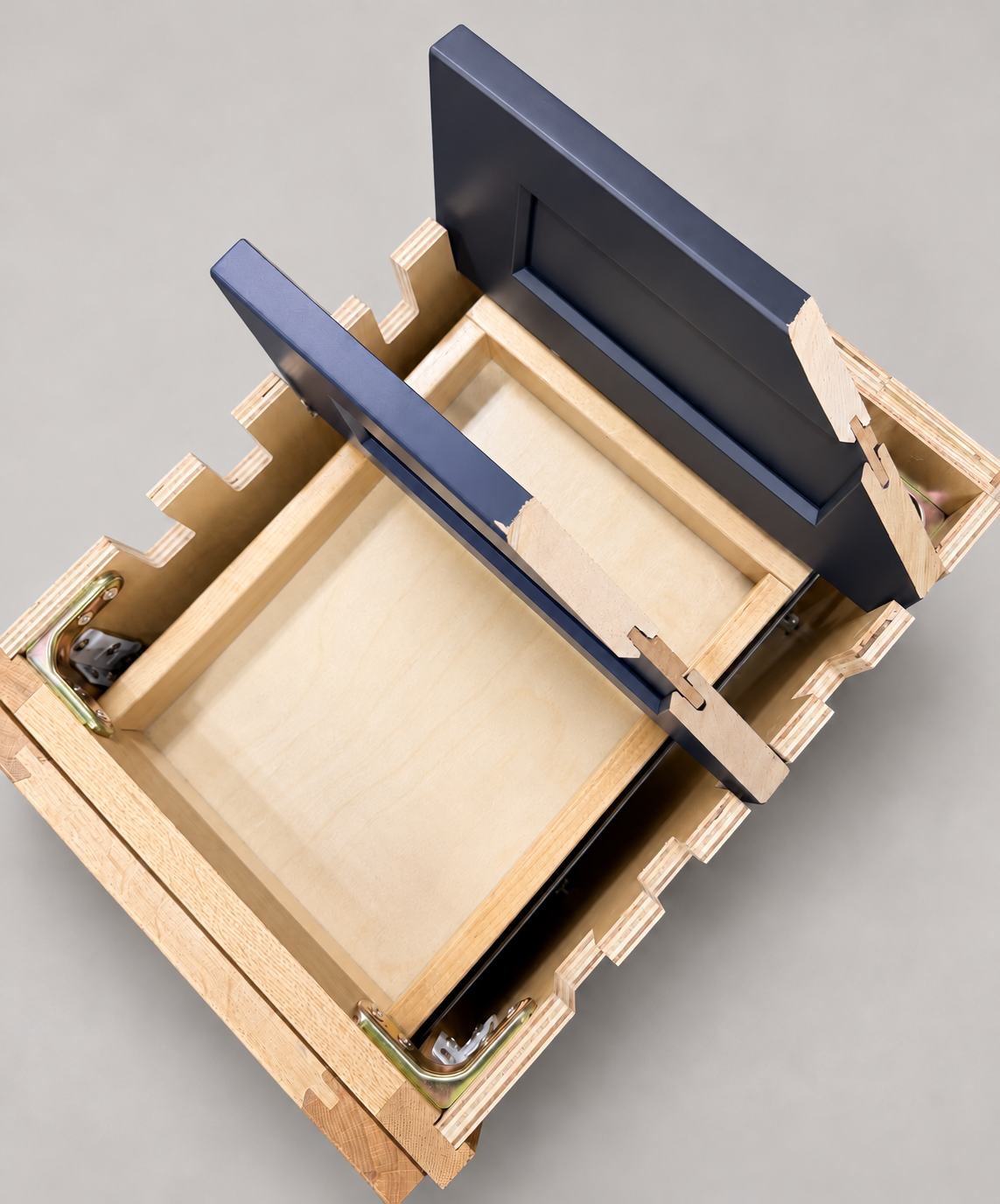
The sample shows the door frame, a separate center panel, the face frame and the cabinet box. Each component has its own place in this Shaker construction.
Shaker construction: door frame, center panel, face frame and cabinet box. The cutaway helps locate these parts; confirm each material in the specifications for the selected cabinet.
01 / Door frame
The Shaker door has rails and stiles around a separate center panel. The frame and center panel are different components; confirm their materials in the specifications for the selected cabinet.
02 / Face frame
The face frame surrounds the opening at the front of the cabinet box and sits behind the doors. The face frame, door frame and cabinet box are separate parts.
03 / Cabinet box
The sample exposes the cabinet sides, interior surfaces and layered edges. The image does not establish the wood species or material specification of a selected cabinet.