Keep a decorative hood enclosure usable after it is finished
Design around the actual insert and the tasks that remain after installation. A component can fit inside the enclosure yet lack the movement needed for cleaning or service.
Approve a decorative hood enclosure only after the selected equipment fits and its necessary access tasks have been explained. The outside shape is not enough. The installer needs an assembly sequence, the household needs ordinary care access, and a service technician may need a different route to particular components. These are related checks, but passing one does not establish all of them.
Define the equipment inside the decorative shape
Record the exact insert or hood liner, blower configuration and applicable accessories. Use their documents to establish the enclosure’s required internal geometry, supports and interface at the lower edge. Have the responsible trades resolve the installation conditions. Do not enlarge a decorative drawing around an assumed equipment box and treat the leftover space as proof of a suitable installation.
Separate the visible surround from the equipment it contains. A deep decorative apron can change the access opening without changing the nominal hood width. A sloping shell can reduce space higher inside the enclosure even when the bottom opening looks generous. Show the relevant section as well as the front elevation so these changes remain visible.
Confirm access while the assembly is being installed
Broan’s cited liner sheet tells installers to retain access for the insert’s electrical connection before completing the custom enclosure. That is an installation-sequence requirement for the covered products, not proof that the same opening handles every future service task.
Ask the installer to identify what must be reached before each permanent part of the enclosure closes. Record which pieces are installed early and which follow the equipment connections and checks. A design that can be assembled only before neighboring cabinets are installed needs that dependency addressed in the work plan, rather than discovered when those cabinets are already finished.
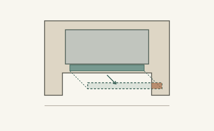
ABCD
Diagram The hypothetical removal path extends beyond the component’s resting outline and meets the decorative edge. This is a geometry example, not a real filter-removal method, construction section or prescribed clearance.
A
Equipment fits inside the shell.
B
The component fits in its installed position.
C
Removal needs a path beyond that position.
D
The decorative edge crosses the proposed path.
Test ordinary care with the enclosure fully finished
Identify the removable parts specified in the actual care instructions and examine the complete movement for taking them out and returning them. Wolf’s cited Pro hood guidance, for example, describes filter removal involving upward and rotating movement. A resting filter outline alone therefore does not describe the task for those units.
In a hypothetical design, a filter fits comfortably behind the lower opening. A deeper trim revision is added afterward. The filter remains hidden and unobstructed at rest, but its required removal movement meets the new edge. The original fit check still looks correct because it never showed the movement. Resolve the decorative detail against the actual care procedure before finishing the enclosure.
Describe service access as a task, not a label
For components beyond ordinary household care, have the installer or appropriate service professional explain the intended access method. Name the component, approach and removable enclosure parts, if any. Do not assume that access through the filter opening is sufficient for every repair, or that the whole insert can be removed through a decorative aperture that merely reveals its underside.
An access panel is useful only if it reaches the required location and can actually be removed in the finished kitchen. Check whether neighboring trim, a cabinet side or the countertop prevents that removal. Any removable surround detail must remain consistent with the selected equipment’s installation requirements; an improvised panel is not permission to alter its support or connections.
Preserve the access method when details change
Keep the equipment identity, installation sequence and agreed care and service methods with the cabinet drawings. Mark which enclosure parts are permanent and which are intended to be removable. Recheck these methods whenever the apron depth, lower opening, molding or adjacent cabinetry changes. A small exterior revision may affect a task that was previously workable.
At completion, review the finished enclosure against the documented method with the appropriate installer. The household should be able to identify the care instructions and ordinary removable parts without guessing. The design succeeds when the hood remains maintainable within its approved installation, while its decorative shape still gives the kitchen the intended appearance.
Pure White
Cream White
Light Warm Gray
Gray
Navy
Black
Oak Tone
Dark Walnut Tone
Design study These finish studies are design references, not a list of currently orderable colors. Screens and lighting change the appearance; compare a physical sample before choosing.See all finish options →
Choose the supported combination and its interface parts before defining the opening. Product width, finished assembly width and countertop cutout are different measurements.
A duct centerline does not describe the space occupied by connectors, bends and installation access. Draw the complete verified route, then decide what storage remains usable.
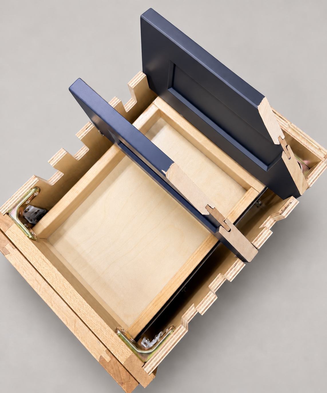
The sample shows the door frame, a separate center panel, the face frame and the cabinet box. Each component has its own place in this Shaker construction.
Shaker construction: door frame, center panel, face frame and cabinet box. The cutaway helps locate these parts; confirm each material in the specifications for the selected cabinet.
01 / Door frame
The Shaker door has rails and stiles around a separate center panel. The frame and center panel are different components; confirm their materials in the specifications for the selected cabinet.
02 / Face frame
The face frame surrounds the opening at the front of the cabinet box and sits behind the doors. The face frame, door frame and cabinet box are separate parts.
03 / Cabinet box
The sample exposes the cabinet sides, interior surfaces and layered edges. The image does not establish the wood species or material specification of a selected cabinet.