Align cabinet fronts around an appliance without changing its required opening
Separate cabinet seams, appliance trim and installation boundaries before choosing an alignment. A clean elevation can use deliberate differences instead of forcing every line through the appliance.
Establish the selected appliance’s required opening and actual front first, then choose which cabinet lines should relate to it. A drawer seam, the edge of an appliance trim piece and an installation boundary are different things. Making them look continuous on an elevation does not make them interchangeable physical edges. A successful composition preserves the functional requirements while giving the visible lines an intentional order.
Identify what each line represents
Use the exact appliance information and cabinet drawings to distinguish the installation opening, visible trim or flange, door, handle and any specified exposed areas. Mark the neighboring drawer and door edges separately. A product photograph can conceal the opening behind overlapping trim, so the visible appliance outline should not be copied as the cabinet cutout.
For the cabinets, distinguish a seam between fronts from a fixed rail or a change of internal compartment. A long drawn line may be only a visual reference. If an apparent seam is meant to be a physical strip, show that strip as a component with its actual location. This prevents a graphic alignment from quietly turning into an obstruction.
Choose a hierarchy of alignments
Identify the lines that matter most in the overall elevation, such as the countertop reference, top of a cabinet bank or a recurring drawer division. Then decide which relationships can vary around the appliance. Trying to align every handle, trim edge and drawer joint can create small front pieces with no useful storage purpose.
Use common physical reference levels when checking the chosen relationships. An appliance positioned from the finished floor and a cabinet drawn from an assumed base can appear aligned in separate sketches but differ when installed together. Reconcile the actual positions before adjusting front proportions merely to improve the graphic.
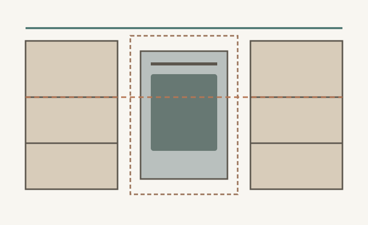
ABCD
Diagram The dashed horizontal line is a visual comparison, not a strip to install across the appliance. The outer dashed reservation and appliance face are deliberately distinct. No dimensions, trim permissions or product opening requirements are specified.
A
A real neighboring drawer division.
B
The separate appliance reservation must remain defined.
C
Extending the visual line does not create a permitted physical strip.
D
A shared upper reference can organize the elevation independently.
Keep installation and operation conditions intact
Retain every opening, support, ventilation provision and exposed feature required by the selected product’s instructions. Do not add an infill, change a trim piece or move an appliance solely to carry a cabinet line through it without confirming that exact arrangement is permitted. A decorative drawing cannot override the installation information.
Also check the moving fronts and handles in the proposed combination. A drawer division that aligns beautifully when closed can place a handle near the path of an appliance door. Use the actual opening geometry and heights. Visual coordination and operating clearance are separate checks, and a successful closed elevation does not complete the latter.
Resolve an attractive line that has become a proposed filler
In a hypothetical design, a neighboring drawer seam crosses the middle of an appliance’s visible front when extended on the elevation. Someone proposes a physical filler at that height to continue the line through the appliance bay. The filler enters the documented appliance opening. The failure is not an untidy drawing; it is that a visual guide has been mistaken for permission to add construction.
Remove that unsupported addition from the proposal and compare legitimate composition choices: accept the appliance as a distinct element, adjust supported neighboring front divisions, or select a different appliance-and-cabinet combination after checking its complete requirements. Do not conceal the mismatch by drawing a trim piece that does not exist in the chosen system.
Retest storage when front divisions change
If the adjacent drawer arrangement changes to improve alignment, verify the corresponding real boxes, internal clearances and retained contents. A shallower-looking top front may not create the storage assumed in the sketch. Preserve the utensils, trays or pots previously assigned there, and show where they go if the supported stack changes.
Review the complete elevation at the intended viewing scale, then save it with the appliance opening detail, cabinet configuration and operating checks. Identify the lines intentionally aligned and the differences intentionally accepted. Recheck after a model or front-system change. The finished decision should be buildable, usable and visually deliberate, with no hidden component added merely to make a line continue.
Pure White
Cream White
Light Warm Gray
Gray
Navy
Black
Oak Tone
Dark Walnut Tone
Design study These finish studies are design references, not a list of currently orderable colors. Screens and lighting change the appearance; compare a physical sample before choosing.See all finish options →
Equal nominal widths do not establish a replacement fit. Compare the old and new assemblies against the same finished boundaries, front plane, countertop and operating tasks.
A tower can change appliance access while removing a prep surface and dividing what remains. Test the same cooking task and retained contents in both complete layouts.
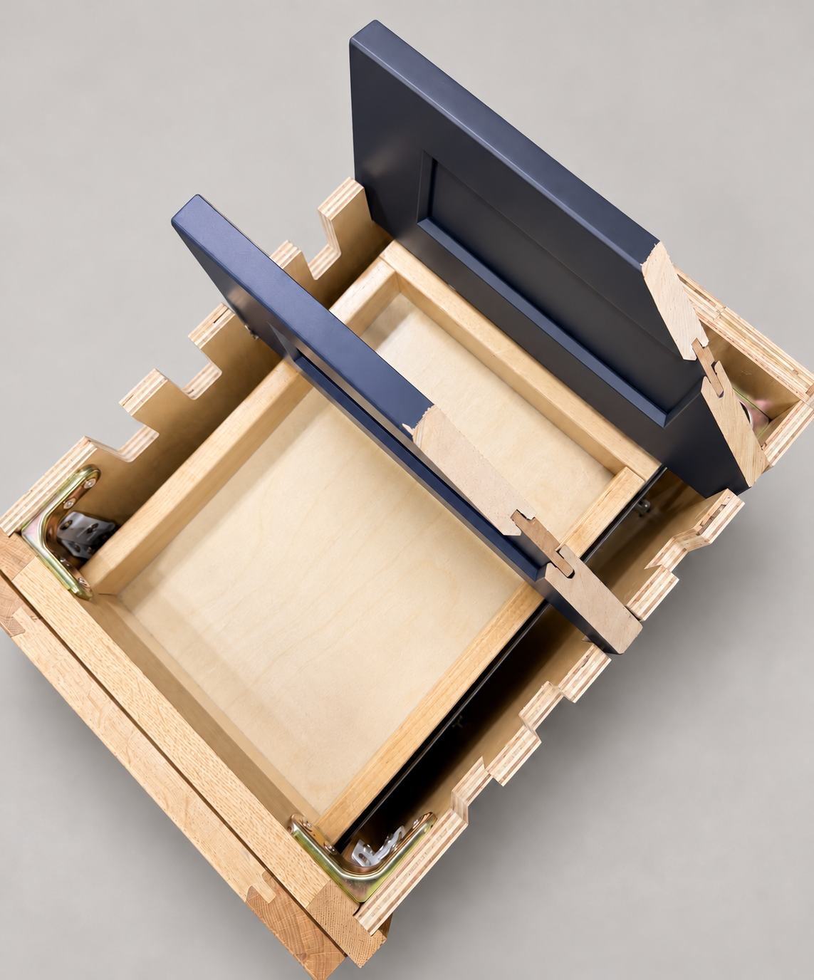
The sample shows the door frame, a separate center panel, the face frame and the cabinet box. Each component has its own place in this Shaker construction.
Shaker construction: door frame, center panel, face frame and cabinet box. The cutaway helps locate these parts; confirm each material in the specifications for the selected cabinet.
01 / Door frame
The Shaker door has rails and stiles around a separate center panel. The frame and center panel are different components; confirm their materials in the specifications for the selected cabinet.
02 / Face frame
The face frame surrounds the opening at the front of the cabinet box and sits behind the doors. The face frame, door frame and cabinet box are separate parts.
03 / Cabinet box
The sample exposes the cabinet sides, interior surfaces and layered edges. The image does not establish the wood species or material specification of a selected cabinet.