What System 32 tells you about a cabinet—and what it does not
The repeated holes inside a cabinet describe a drilling grid, not the cabinet width. Learn how to read the pitch, count intervals and compare a hardware drawing before ordering fitted storage.
A cabinet described as System 32 uses a coordinated drilling arrangement. It does not mean the cabinet is that many inches wide, and it does not guarantee that every pullout advertised for the system will fit. For a buyer, the useful question is whether the cabinet and the selected fitting share the required mounting geometry while still providing enough space for the moving assembly.
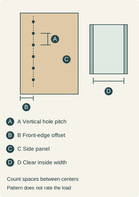
Hettich’s System 32 guide shows 5 mm holes on a 32 mm vertical pitch, with the front hole line centered 37 mm behind the side-panel front edge. These are drilling-pattern dimensions, not cabinet-width dimensions.
Look into the cabinet from the front. The hole line normally runs up a side panel, so moving between holes changes height. The cabinet’s clear width runs between its sides. A shelf can therefore use the same hole pattern in a narrow cabinet and a wider one while requiring a different shelf length. Its support spacing and loading behavior still need their own specification.
The front-edge offset is measured across the side panel toward the back. It is not measured from a protruding door face or from the room wall. A photo taken with the door shut can obscure that distinction. Ask for a view of the actual side-panel edge and the mounting hole centers when confirming an accessory.
Count intervals, not the circles
In a hypothetical inspection, seven consecutive hole centers are visible. There are six intervals between the first and last. At a 32 mm pitch, the total center-to-center span is 6 × 32 = 192 mm. Multiplying the seven holes by the pitch would give 224 mm, which includes an extra interval that is not present.
This check is useful when a seller sends a ruler alongside a long row: a longer span can make a small pitch difference easier to notice than a single close-up. Keep both ruler ends on hole centers and check that no hole has been skipped. A camera held at an angle can distort the reading, so treat a photograph as identification evidence rather than a precision inspection.
Do not round a nearly matching imperial spacing into a metric match. Hardware may allow specific adjustment, but adjustment range belongs to that fitting’s instructions. It is not permission to force misaligned fasteners into the panel or enlarge holes until they accept them.
Teaching example Conceptual side-panel view. The circles are hole centers; the dimension arrow spans neighboring centers. The front-edge offset is a separate horizontal measurement. Clear inside width runs between the side panels and cannot be read from this side-panel pattern. Drawing is not a drilling template.
A matching pitch still leaves several fit questions
A mounting plate may use the intended grid and still be wrong for the hinge arm or door overlay. A runner may line up at the front but require a different rear fixing position, drawer preparation or cabinet depth. A pullout may fit between the sides but collide with the open door. Check these dimensions on the selected hardware drawing rather than treating the grid name as a universal adapter.
Also distinguish hole diameter from fastener type. A visible hole does not tell you which thread, dowel, insertion depth or panel material the fitting requires. Existing holes can be worn or damaged. A replacement that shares the nominal pattern still needs a sound attachment using the manufacturer’s specified method.
Do not use the number of available shelf positions as evidence of storage capacity. A densely drilled panel may offer many arrangements, while the shelf, supports, cabinet joints and wall attachment impose separate limits. The grid organizes placement; it does not publish a load rating for the completed cabinet.
Use the pattern to narrow the order, then check the assembly
Consider an owner ordering an internal tray. The seller confirms the side-hole pitch and assumes the tray fits. The hardware drawing then shows that the tray’s moving frame occupies more clear width than the cabinet provides, even though its mounting locations align. In this hypothetical project, the owner keeps the cabinet and selects a narrower assembly whose drawing confirms the required hole pattern, inside clearance and door-open passage. Moving the original frame to another pair of holes would not create width.
Send the cabinet model, clear opening and internal dimensions together with the hole pattern and the intended accessory model. Include the door-open view, because the narrowest passage can be at the entrance rather than between the bare sides. Keep the supplier’s completed fit confirmation with the cabinet order.
For a new kitchen, this information also makes later replacements easier. Save the hardware model and installation drawing instead of relying on the phrase “European hardware.” A known drilling system is useful documentation, but the actual cabinet and fitting remain the things being purchased.
Pure White
Cream White
Light Warm Gray
Gray
Navy
Black
Oak Tone
Dark Walnut Tone
Design study These finish studies are design references, not a list of currently orderable colors. Screens and lighting change the appearance; compare a physical sample before choosing.See all finish options →
Some supports do more than carry weight. Determine whether the shelf rests on pins or engages a retaining feature before changing its height or ordering replacement parts.
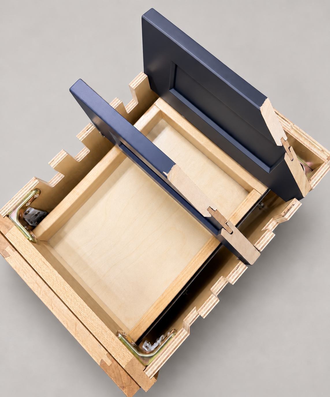
The sample shows the door frame, a separate center panel, the face frame and the cabinet box. Each component has its own place in this Shaker construction.
Shaker construction: door frame, center panel, face frame and cabinet box. The cutaway helps locate these parts; confirm each material in the specifications for the selected cabinet.
01 / Door frame
The Shaker door has rails and stiles around a separate center panel. The frame and center panel are different components; confirm their materials in the specifications for the selected cabinet.
02 / Face frame
The face frame surrounds the opening at the front of the cabinet box and sits behind the doors. The face frame, door frame and cabinet box are separate parts.
03 / Cabinet box
The sample exposes the cabinet sides, interior surfaces and layered edges. The image does not establish the wood species or material specification of a selected cabinet.